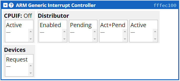
The CPUlator Computer System Simulator has a number of programmable simulated devices based upon the DE1-SoC computer board. The simulated devices appear in the Devices window:
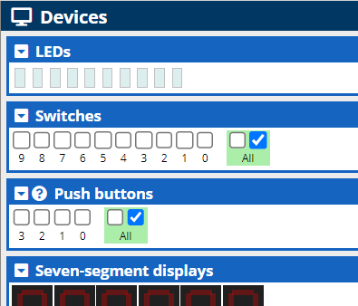
All individual devices panel have a title bar, like:

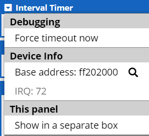
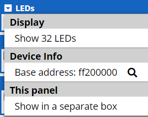
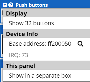
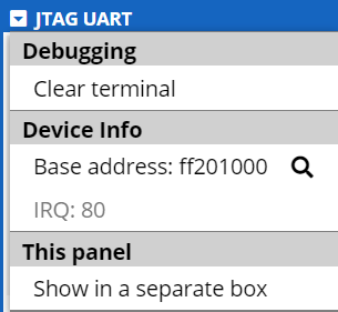
All title bars have a drop-down menu button ![]() that gives access to an options menu
for each device. Although the options vary from device to device, every
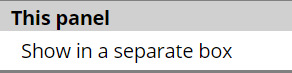
menu has a This panel option that allows you to detach the
device from the Devices window and move it within the browser.
that gives access to an options menu
for each device. Although the options vary from device to device, every
menu has a This panel option that allows you to detach the
device from the Devices window and move it within the browser.
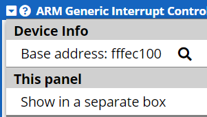
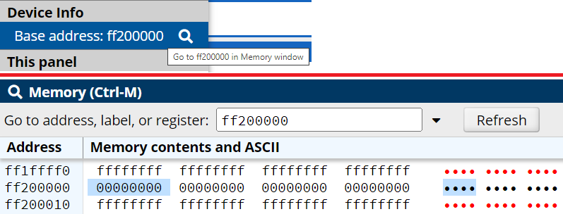
All title bars have a device's hexadecimal base address ![]() which is used to read from or write to the device memory. The menu lists
a Device Info option that when clicked shows the contents of
memory at that location in the Memory window.
which is used to read from or write to the device memory. The menu lists
a Device Info option that when clicked shows the contents of
memory at that location in the Memory window.
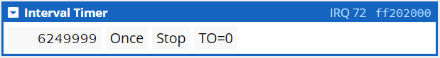
Some title bars have an IRQ (interrupt request) value ![]() that is used
to interface with that particular device. A few title bars have a help
button
that is used
to interface with that particular device. A few title bars have a help
button ![]() that
provides extra help on the use of the device.
that
provides extra help on the use of the device.
There are 10 output-only red LEDs which are set by writing to bits 0 - 9 of the LED memory. Bits 10 - 31 are unused. A 1 turns the LED on, a 0 off.
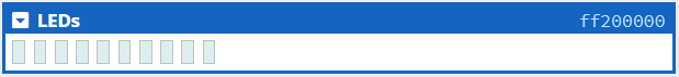
The LEDs menu has an option to show 32 LEDS, in which case bits 0 - 31 are used. (The physical device this simulates has only 10 LEDS.)
Assembly Example
Display alternating on/off LEDs:
.equ LEDS, 0xff200000 // LEDS base address

.org 0x1000
.text
.global _start
_start:

// alternating 10 LEDS - 0b 0010 1010 1010 - 0x2AA
ldr r0, =LEDS
movw r1, #0x2AA  // alternating LEDs bit pattern
str r1, [r0]

_stop:
b _stop
.end
which produces: ![]()
There are 10 input-only switches which are read from bits 0 - 9 of the switch memory. A switch bit is set to 1 if the switch is pressed, 0 otherwise. Bits 10 - 31 are unused.
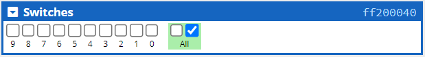
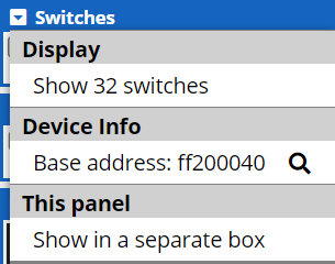
The Switches menu has an option to show 32 switches, in which case bits 0 - 31 are used. (The physical device this simulates has only 10 switches.)
Assembly Example
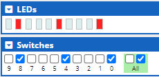
Copy Switches to LEDs:
.global _start
_start:

.equ LEDS,      0xff200000  // LEDS base address
.equ SWITCHES,  0xFF200040  // Switches base address

ldr r0, =SWITCHES
ldr r1, =LEDS

TOP:
ldr r2, [r0]    // Read in switch - active pressed
str r2, [r1]    // Copy to LEDs
b TOP
The following figure shows how the code above sets LEDs based upon the switches pressed.
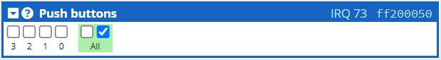
There are 4 input-only push buttons which are read from bits 0 - 3 of the push button memory. A push button bit is set to 1 if the button is pressed, 0 otherwise. When a button is released another part of the push button register is set to 1. This is called edge capture. Thus programs can both capture when a button is held down and when it is released.
The Control Registers
The push buttons are controlled by a single 32-bit register:
| Field | Purpose |
|---|---|
| Data | Each bit represents one of the four push buttons. The bit have a value of 1 when the corresponding button is pushed, and 0 when released. |
| Interrupt Mask | Enables interrupts for each button. Set bit to 1 to enable the interrupt for the corresponding bit/button in the Data section. |
| Edge Capture | The bit is high if the corresponding bit/button in Data changes its value from 1 to 0, i.e. if the button is released. Writing a 1 here clears this register. |
Assembly Example
Copy Switches to LEDs:
.global _start
_start:

.equ PUSH,  0xff200050  // Push buttons base address
.equ LEDS,  0xff200000  // LEDS base address

ldr r0, =PUSH
ldr r1, =LEDS

TOP:
ldr r2, [r0]    // Read in push buttons - active pressed
str r2, [r1]    // Copy to LEDs
b TOP
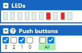
The following figure shows how the code above sets LEDs based upon the buttons pushed.
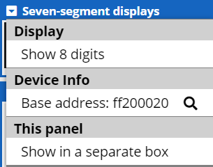
There are 6 output-only red seven segment displays, each of which can be used to display digits and a (limited) range of letters. Each segment of a display can be addressed individually to show these digits and letters.
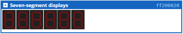
The individual displays are labelled here as HEX0 to HEX5. (The physical
DE1-SoC has six displays, the CPULator simulator has an extra two
displays we will label HEX6 and HEX7.) Individual segments within a
display are turned on and off by assigning 1 (on) or 0 (off) to seven
bits in a group of 8 bits. (The highest bit is ignored). The 32 bits
that control each set of four displays are at addresses 0xFF00020
and 0xFF00030.
| Address | Bits | |||||||||||||||
|---|---|---|---|---|---|---|---|---|---|---|---|---|---|---|---|---|
| 0xFF00020 | 31 | 30 - 24 | 23 | 22 - 16 | 15 | 14 - 8 | 7 | 6 - 0 | ||||||||
HEX3 |
HEX2 |
HEX1 |
HEX0 |
|||||||||||||
| 0xFF00020 | 31 | 30 - 24 | 23 | 22 - 16 | 15 | 14 - 8 | 7 | 6 - 0 | ||||||||
HEX7 |
HEX6 |
HEX5 |
HEX4 |
|||||||||||||
The following diagram shows how the bit numbers reference a specific segment, and examples of numbers displayed by setting the matching bits to 1.
The menu has an option to show 8 displays, in which case bits 0 - 31 of the second 32 bit value are also used.
Assembly Example
Write the digits 845 from the previous example to the rightmost three seven segment displays (HEX0 to HEX2):
// Constants
.equ SEVEN_SEGMENT_1, 0xff200020 // first four 7-Segment Displays base address
// Define digit display bit offsets
.equ HEX1,  8
.equ HEX2,  16
// Define block digit segments
.equ FOUR,  0b01100110
.equ FIVE,  0b01101101
.equ EIGHT, 0b01111111

.org 0x1000
.text
.global _start
_start:

ldr r0, =SEVEN_SEGMENT_1    // load first seven segment address
ldr r1, =FIVE               // load segments definition of 5
ldr r2, =FOUR               // load segments definition of 4
orr r1, r1, r2, lsl #HEX1   // or definitions of 5 and 4 - shift 4 to proper digit
ldr r2, =EIGHT              // load segments definition of 8
orr r1, r1, r2, lsl #HEX2   // or definitions of 5, 4, and 8 - shift 8 to proper digit
// equivalent to:
// ldr r1, =#0x007F666D
str r1, [r0]                // write all digits to seven segment display

_stop:
b _stop
.end
which produces:
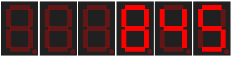
This sample code constructs a register with the segment definitions of the digits 5, 4, and 8 by or-ing and offsetting those separate digit segment definitions. The point of the constants is to make the code easily readable.
The JTAG (Joint Test Action Group) UART (Universal Asynchronous Receiver/Transmitter) simulates simple character-based input (keyboard) and output (console). Character input is handled by the 64 byte Read FIFO queue, and character output by the 64 byte Write FIFO queue. (In the actual hardware the sizes of the Read and Write FIFOs are adjustable.) Text is entered into and displayed in the Terminal area. The UART displays only standard ASCII characters.
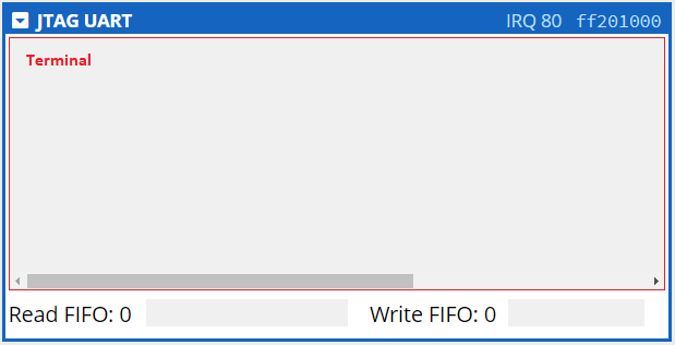
The Read FIFO Queue
Enter characters into the UART by clicking on the Terminal area
and typing. These characters then appear in the Read queue in
hexadecimal format. A maximum of 64 characters can be stored in the Read
FIFO. The number of characters currently in the Read FIFO is displayed
beside the title
Read FIFO:
For example, typing the 10-character string
Hi There.\n
(
\n
means 'press the Enter key') on the Terminal appears as:
![]()
in
the Read FIFO.
Characters entered beyond the 64 byte limit are ignored and no more characters may be entered into the Read FIFO until the queue is drained.
The Write FIFO Queue
To appear on the Terminal characters must be moved from the Read FIFO to the Write FIFO. Characters in the Write FIFO are automatically removed from the queue and displayed in the Terminal over time. This simulates the finite time it takes to move data from the Write FIFO to an output device in the actual hardware. Although the Write FIFO drains very quickly, it is not infinitely fast. Thus it is possible to overflow the Write FIFO and cause a program using it to crash.
The Read and Write queues can be controlled by the UART Control Registers.
The Control Registers
The Terminal and queues are controlled by the UART Control Registers, which are two 32-bit registers:
| Field | Purpose |
|---|---|
| RAVAIL | Number of characters available to read from the Read FIFO |
| RVALID | Read data is valid: 1 if data can be copied from the Read FIFO, 0 otherwise |
| DATA | 1 byte of data for either reading and writing |
| WSPACE | The bytes available in the Write FIFO |
| AC | (not used in this course) Indicates that there has been JTAG activity since the bit was cleared. Writing 1 to AC clears it to 0. |
| WI | (not used in this course) Write interrupt is pending |
| RI | (not used in this course) Read interrupt is pending |
| WE | (not used in this course) Enable write interrupts |
| RE | (not used in this course) Enable read interrupts |
The Data Register both sends and receives data depending on the instruction executed:
-
ldr ra, [rb] // rb: contains address of Data Register -
removes a byte from the Read FIFO and copies it to the
DATA
field of the Data Register. The contents of the Data Register are then
copied to the target register
ra. The 16-bit RAVAIL field is decremented. The RVALID bit is 1 if data is still available in the Read FIFO, and 0 if the Read FIFO is empty. -
strb ra, [rb] // rb: contains address of Data Register -
copies the lowest byte of register
rato the DATA field of the Data Register, inserts that DATA field byte into the Write FIFO, and decrements the 16-bit WSPACE field in the Control Register. When this byte moves to the front of the Write FIFO queue it will be removed and displayed on the Terminal.
The menu has an option to clear the Terminal, but not the Read FIFO. The Read FIFO must be read from to empty it. (The Write FIFO drains itself over time.)
Assembly Examples
Write the contents of a text string from memory to the UART Terminal:
.equ UART_BASE, 0xff201000   // UART Data Register address
.equ WSPACE_MASK, 0xffff0000 // Control Register WSPACE mask
.org 0x1000
.text
.global _start
_start:

ldr  r0, =UART_BASE    // set UART Data Register address
ldr  r1, =TEST_STRING  // set sample test string address
ldr  r2, =WSPACE_MASK  // assign WSPACE_MASK to a register - too large to use as immediate value

/* Write the entire string to the UART Terminal. */
LOOP:
ldrb r3, [r1], #1  // load a character from the string, increment to next character
cmp  r3, #0        // compare character to NULL
beq  _stop         // stop when NULL character is found

WSPACE:            // verify that the Write FIFO has space
ldr  r4, [r0, #4]  // load Control Register
tst  r4, r2        // apply WSPACE mask to control register to isolate WSPACE field
beq  WSPACE        // recheck WSPACE field until it is non-zero

strb r3, [r0]      // copy the character to the Write FIFO
b    LOOP

_stop:
b _stop

.data
// NULL-terminated test string
TEST_STRING:
.asciz    "This is a text string that is too long\nand will cause a problem by overflowing the Write FIFO.\n"
.end
which produces:
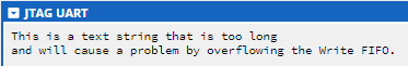
Without the WSPACE: loop the program prints only:

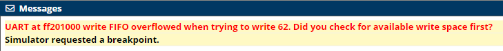
and writes the following error to the Messages dialog:
Write the contents of the Read FIFO to a memory string buffer until the string buffer is full. You can type up to 80 characters into the UART Terminal before the program ends:
.equ UART_BASE, 0xff201000  // UART Data Register address
.equ SIZE, 80               // Size of string buffer storage (bytes)
.equ VALID, 0x8000          // Mask for RVALID field in Data Register

.org 0x1000
.text
.global _start
_start:

ldr  r0, =UART_BASE      // set UART Data Register address
ldr  r1, =STRING_BUFFER  // set string buffer address
add  r2, r1, #SIZE       // store address of end of buffer

LOOP:
ldr  r3, [r0]            // read Data Register
tst  r3, #VALID          // check RVALID field (bit 15) for data in Read FIFO
beq  LOOP                // if no data in Read FIFO, keep checking
strb r3, [r1], #1        // else store character to memory, increment address
cmp  r1, r2              // end program if string buffer full
beq  _stop
b LOOP

_stop:
b    _stop

.data  // Data section
STRING_BUFFER:    // String storage buffer
.space    SIZE
.end