The CPUlator: https://cpulator.01xz.net/?sys=arm-de1soc.
Assembly I/O
On a 'real' DE1-SoC computer, we can connect to external devices such as
keyboards and monitors, and communicate with this devices through its
JTAG (named after the Joint
Test Action Group which codified it) UART (Universal
Asynchronous Receiver/Transmitter). The simulator cannot communicate
with actual external devices or files, but it can simulate writing to
and reading from a UART in its JTAG UART box. The box gives the
base address of the UART at 0xff201000, and we use this
address to communicate with the simulated UART.
The WriteString subroutine prints a null-terminated string
to the UART:
// Subroutine constants
.equ UART_BASE, 0xff201000     // UART base address

WriteString:
/*
-------------------------------------------------------
Writes a null terminated string to the UART.
-------------------------------------------------------
Parameters:
  r4 - address of string to print
Uses:
  r0 - holds character to print
  r1 - address of UART
-------------------------------------------------------
*/
stmfd sp!, {r0, r1, r4}  // preserve temporary registers
ldr   r1, =UART_BASE     // get address of UART

wsLOOP:
ldrb  r0, [r4], #1       // load a single byte from the string
cmp   r0, #0
beq   _WriteString       // stop when the null character is found
str   r0, [r1]           // copy the character to the UART DATA field
b     wsLOOP
_WriteString:
ldmfd sp!, {r0, r1, r4}  // recover temporary registers
bx    lr                 // return from subroutine
and to call this subroutine we issue the instructions:
ldr r4, =address of string
bl  WriteString
The main program is:
ldr r4, =First
bl  WriteString
ldr r4, =Second
bl  WriteString
ldr r4, =Third
bl  WriteString
ldr r4, =Last
bl  WriteString

_stop:
b    _stop
The strings are placed in memory by:
.data
.align
// The list of strings
First:
.asciz  "First string"
Second:
.asciz "Second string"
Third:
.asciz "Third string"
Last:
.asciz "Last string"
_Last:    // End of list address
The .asciz directive defines a null-terminated string, and
these strings can be viewed in memory.
Download the full program: write_demo.s.
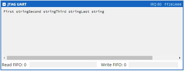
Upon execution, you should see the string(s) output in the UART box:
You can clear the contents of the UART (but not the queues) by clicking on the upper-left corner of the UART box and choosing Clear terminal from the drop-down menu.
Reading a String
The ReadString subroutine reads a text string from the UART
to memory:
ReadString:
/*
-------------------------------------------------------
Reads an ENTER terminated string from the UART.
-------------------------------------------------------
Parameters:
  r4 - address of string buffer
Uses:
  r0 - holds character to print
  r1 - address of UART
-------------------------------------------------------
*/

stmfd sp!, {r0, r1, r4}     // preserve temporary registers
ldr   r1, =UART_BASE        // get address of UART

rsLOOP:
ldr  r0, [r1]      // read the UART data register
tst  r0, #VALID    // check if there is new data
beq  _ReadString   // if no data, exit subroutine
strb r0, [r4]      // store the character in memory
add  r4, r4, #1    // move to next byte in storage buffer
b    rsLOOP
_ReadString:
ldmfd sp!, {r0, r1, r4}     // recover temporary registers
bx    lr                    // return from subroutine
Download the full program: read_demo.s.
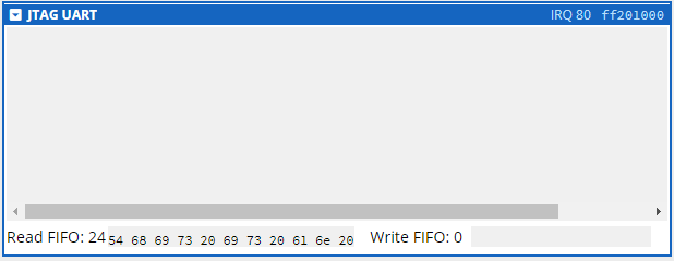
Input in the UART box shows up as ASCII code in the Read FIFO: text field:
Having read your input from the UART box, the results should show up in memory:
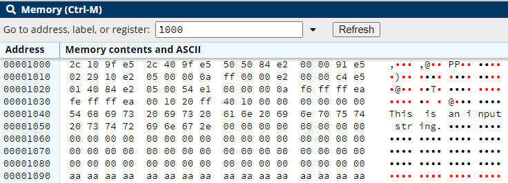
Note that the unused portion of the buffer shows up as black dots, indicating that the memory has been set aside for storage, while unallocated memory shows up as red dots.
The UART Control Registers
The constant VALID is a byte mask that control the
use of the UART. The UART has two 32-bit control registers at memory
location 0xff201000 (here named UART_BASE for
readability). The control registers are mapped as:
Characters received by the UART are stored in a 64-byte (character) queue called the read FIFO. Characters written to the UART are stored in a 64-byte queue called the write FIFO. (Both can be seen at the bottom of the UART dialog box in the CPULator.)
Data received by the UART (typed by you in the CPULator, or received from an external source in the physical computer) is stored in the read FIFO. The RAVAIL field contains the number of characters in the read FIFO, and the RVALID bit is set to 1. The lines:
.equ UART_BASE, 0xff201000 // UART base address
…
.equ VALID, 0x8000  // Valid data in UART mask
…
ldr  r1, =UART_BASE
…
ldr  r0, [r1]       // read the UART data register
tst  r0, #VALID     // check if there is new data
beq  _stop          // if no data, return 0
…
determines if there is data in the read FIFO by checking whether the RVALID bit is set to 1. It does so by:
- first loading the contents of the UART data register into
r0. This is necessary because the UART data register is really just a location in memory, and ARM does not allow the direct comparison of values in memory - they must be loaded into a register. tst-ing the contents of the UART data register (now inr0) against theVALIDmask. In hex this mask is0x8000, which is 1000 0000 0000 0000in binary. Note that the 15th bit of this value is set to 1 - this matches the location of the RVALID bit in the UART data register.tst-ing against this binary value returns a 0 if the 15th bit of the target is 0, and 1 if the 15 bit of the target is 1. The result of thetstsets appropriate flags to be used with the branch instructions, and then the result is thrown away. (For example, theZ(Zero) flag is set if a value is = 0, and 1 if not. Thebeqinstruction looks at theZflag to determine if a value is indeed 0.) Simply put, this is a technique to determine if RVALID is true or false.- using the
beqbranch instruction to branch to_stopif RVALID is false (0), and keep going if RVALID is true (1).
The actual characters in the read FIFO are copied into memory by the lines:
.equ UART_BASE, 0xff201000 // UART base address
…
ldr  r1, =UART_BASE
ldr  r4, =TEXT_strING
…
strb r0, [r4]      // store the character in memory
add  r4, r4, #1    // move to next byte in storage buffer
…
which do so by:
- using the same line as above to copy the contents of the UART
data register into
r0. - copying this character now in
r0to the memory location stored inr4with the linestrb r0, [r4]. TheBon thestrinstruction instructs ARM to copy only a single byte to memory, rather than the default 4-byte word. There is other data in the register beyond the right-most byte, but it is ignored. - moving to the next byte location in memory with the instruction
add r4, r4, #1.
As each character is read from the read FIFO queue, the 16 byte value in the RAVAIL field is decremented by 1. When the read FIFO queue has been fully read, RAVAIL is set to 0, RVALID field is set to 0, and the DATA field is undefined.
Directives
-
.asciz -
Defines a NUL-terminated (a 0x00 byte) string literal.
-
.ascii -
Defines a string literal with no NUL termination.
-
.end -
Defines the end of program. Optional, but recommended. Everything after this directive is ignored.
Instructions
The instructions used to test registers: tst, and and.
-
tst -
Performs a bitwise
andoperation on the values inrnandOperand2. The result is not applied to the register. TheN(negative) andZ(zero) flags are updated according to the result.Formats:
tst rn, Operand2-
rn - The register to test.
-
Operand2 -
The mask to apply to the
rn.
The instruction:
tst r0, #0x1ands the value stored in
r0against the immediate value0x1(1 decimal). In essence it is testing to see whether the first bit of the register is 1 or 0. If the first bit ofr0is 0, theZflag is set to 1, otherwise it is set to 0. In both cases theZflag is 0. -
-
and -
Performs a bitwise
andoperation on the values inrnandOperand2, and writes the result to the registerrd. TheN(negative) andZ(zero) flags are updated according to the result only if the conditionSis used.Formats:
and{cond} rd, rn, Operand2-
{cond} -
The optional condition to apply to the instruction. Using
Supdates the appropriate condition codes. -
rd - The destination register.
-
rn - The register to and against.
-
Operand2 -
The mask to apply to the
rn.
The instructions:
and r0, r1, #0x1
andS r2, r3, #0xF
The first line ands the value stored in
r1against the immediate value0x1(1 decimal) and puts the result intor0. In essencer0will contain the values 0 or 1, depending on the original value inr1. The condition flags are not set.
The second line ands the value stored inr3against the immediate value0xF(15 decimal) and puts the result intor2. In essencer2will contain only the first 4 bits ofr3. The condition flags are set because of the use of theScondition on the instruction. -
tst and and both apply a Boolean and against
a value. tst does not preserve the result of that Boolean
operation but it does update the appropriate flags, while and
preserves the result of that Boolean operation and updates the flags
only if the appropriate condition is set. Using and is a
particularly useful way to extract specific bits of a register.
-
Complete the code in l08_t01.s. Update the
WriteStringsubroutine so that it prints an end of line (ENTER) character at the end of the string it sends to the UART. (The enter character is0x0A- define this value as a constant namedENTER.)
-
Complete the code in l08_t02.s. Update the
ReadStringsubroutine so that it stops reading from the UART if the string buffer is full, i.e. if the number of characters stored in the string memory reachesSIZE. Pass the size of the buffer throughr5.
-
Complete the code in l08_t03.s. Update the
EchoStringsubroutine so that it reads a string from the UART and writes that string back to the UART until the Enter key is pressed. Do not use any memory.
Zip your files together in zip file named login_l08.zip (using your Laurier login, of course) and submit that zip file to the MLS dropbox.