The CPUlator: https://cpulator.01xz.net/?sys=arm-de1soc.
Breakpoints
Rather than trace through an entire program, sometimes we wish to pause the program at a particular spot (the breakpoint) to examine the contents of the registers or memory. All assembly language development environments allow the user to set breakpoints. Once you start writing programs with loops, you will want to use single step tracing selectively, typically from a breakpoint.
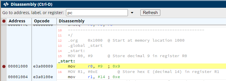
In the CPUlator simulator you set or remove breakpoints by clicking in the left-most gray column (with the red dot at the top) in the Disassembly window, next to the instruction where you want the breakpoint.
The breakpoints tab (in the Registers area) shows the addresses of any current breakpoints set.
The following program uses the branch instruction bgt
(Branch if Greater Than) to execute a loop:
.org    0x1000  // Start at memory location 1000
.text           // Code section
.global _start
_start:

// Store data in registers
mov r3, #5      // Initialize a countdown value
TOP:
sub r3, r3, #1  // Decrement the countdown value
cmp r3, #0      // Compare the countdown value to 0
bgt TOP         // Branch to TOP if greater than 0
// End program
_stop:
b _stop

.end
Download the full program: count0.s.
Execute the program to see how the value in r3 is
decremented from 5 to 0. You may also step through it line by line using
the Step Into button. However, if the loop had 20 lines and
executed 40 times, that would be a lot of stepping. Instead,
set a breakpoint on the line containing the bgt
instruction. Run the program as usual, and see how it stops only on the
line containing bgt. This allows you focus on the effect of
the branch.
The Condition Flags
A condition flag is set by the execution of an instruction. Not
all instructions change the current execution conditions, and some are
specifically designed to do so, such as the cmp
instruction.
The current condition flags are displayed in the CPUlator Registers
section beside the CPSR (Current Program Status Register),
or register r16:

Grayed-out letters have a value of 0, bold letters have a value of 1. In
the image above, I and SVC are set to 1, and
all others are set to 0.
| Flag | Name | Description |
|---|---|---|
N |
Negative | Set to 1 if the result of the previous instruction is negative, 0 otherwise. |
Z
| Zero | Set to 1 if the result of the previous instruction is zero, 0 otherwise. |
C |
Carry | Set to 1 when the operation results in a carry, or when a
subtraction results in no borrow, 0 otherwise.
C is set in one of the following ways:
|
| V | Overflow | Set to 1 when the operation causes overflow, 0 otherwise.
Overflow occurs if the result of a signed addition, subtraction, or comparison is larger than the CPU supports. |
| I | Ignore | |
| SVC | Ignore |
Condition Codes
In Lab 1, we showed the general syntax for most ARM instructions as:
{label} operation{condition code}{flags} Rd, Operand1{, Operand2}
A condition code is a condition applied to an instruction to determine if that instruction will be executed. The condition codes, and the condition flags that determine whether their instruction is executed are:
| Code | Description | Flags |
|---|---|---|
| EQ | Equal / equals zero | Z |
| NE | Not equal | !Z |
| CS / HS | Carry set / unsigned higher or same | C |
| CC / LO | Carry clear / unsigned lower | !C |
| MI | Minus / negative | N |
| PL | Plus / positive or zero | !N |
| VS | Overflow | V |
| VC | No overflow | !V |
| HI | Unsigned higher C and | !Z |
| LS | Unsigned lower or same | !C or Z |
| GE | Signed greater than or equal | N == V |
| LT | Signed less than | N != V |
| GT | Signed greater than | !Z and (N == V) |
| LE | Signed less than or equal | Z or (N != V) |
| AL | Always (default) | any |
Thus, addeq is executed only if the EQ
condition is met, blt is executed only if the LT
condition is met, etc. A condition is met if a condition flag
is set.
Instructions
-
cmp(Compare) -
Format:
cmp rn, Operand2Compares two operands and sets the condition flags according to the result of the comparison. The comparison is done as
rn - Operand2(the result is discarded).Operand2may be a register or an immediate value. -
Bxx(Branch) -
Format:
Bxx Labelwhere
xxis one of the branch codesThe branch instruction depends on the result of an instruction called previously in the program. This instruction must have the potential to change the condition codes. The
cmpinstruction is often used for this as its only purpose is to compare registers and update the condition codes on the basis of the results of the comparison.
Delay Timer
The following program uses the board timer to set a delay and writes data to LEDs:
/*
* This program provides a simple example of code for the ARM. The program
* performs the following:
* 1. starts the ARM private timer
* 2. loops forever, rotating the LEDs when the timer expires
*/
// Constants
.equ TIMER, 0xfffec600
.equ LEDS,  0xff200000
.equ LED_BITS, 0x0F0F0F0F
.org 0x1000 // Start at memory location 1000
.text           // Code section
.global _start
_start:

ldr r0, =LEDS       // LEDs base address
ldr r1, =TIMER      // private timer base address
ldr r2, =LED_BITS   // value to set LEDs
ldr r3, =200000000  // timeout = 1/(200 MHz) x 200x10^6 = 1 sec
str r3, [r1]        // write timeout to timer load register
mov r3, #0b011      // set bits: mode = 1 (auto), enable = 1
str r3, [r1, #0x8]  // write to timer control register
LOOP:
str r2, [r0]        // load the LEDs
WAIT:
ldr r3, [r1, #0xC]  // read timer status
cmp r3, #0
beq WAIT            // wait for timer to expire
str r3, [r1, #0xC]  // reset timer flag bit
ror r2, #1          // rotate the LED bits
b LOOP

.end
Download full program: timer1.s.
The details of how the timer works and the LEDs are set are left to another lab. The delay loop shown in this program is a polling loop. The delay loop constantly checks the value of the board timer until it reaches 0, the LEDs are rotated, then the timer is set back to 1 second and turned back on.
Put your written answers to these tasks into the file answers.txt and
submit it as part of your zip file.
-
Copy the contents of
count1.sinto the CUPlator. Rewrite the program so that is uses thebge(Branch while Greater than or Equal to) instruction rather thanbgtas the branch decision instruction, and run it.What is the value in
r3when the loop is done in both signed decimal and hexadecimal?
-
Copy the contents of
count2.sinto the CPULator. Rewrite the program so that the initial values are stored in memory under the labelCOUNTERand read intor3, rather than using an immediate value assign. (Add this label and data in a.datasection as shown in last week's Debugging lab.What is the address of
COUNTERin hexadecimal?
-
Copy the contents of
count3.sinto the CPUlator. Rewrite the program so thatLED_BITSis stored in a memory location rather than defined with an.equ, and add a memory location namedDELAY_TIMEthat stores the delay time200000000rather than defining it in the body of the program.Alter these values in memory, and compile and run the program again. What effects do your changes have?
Zip your files together in zip file named login_l03.zip (using your Laurier login, of course) and submit that zip file to the MLS dropbox.